1
Pentek Homepage
Follow Us On LinkedIn Follow Us On Twitter Follow Us On YouTube Follow Us On Facebook Register AccountRegister Login AccountSign In
Board Selector   |  Recorder Selector   |  
Search:  
Home > Tutorials > Development tactics and techniques for SFF RF Signal Recorders
Tutorial Header

Development Tactics and Techniques for Small Form Factor (SFF) RF Signal Recorders

by Chris Tojeira, Recording Systems Director

This article discusses the engineering considerations and design techniques used to develop a small form factor (SFF) rugged recorder that can handle the extremely high data rates associated with very wide bandwidth RF signal recording. It is intended to provide engineers with ideas on how to bring this capability into confined and often extreme environments while focusing on military specification compliance, SWaP, and ease of use with confidence.

XMC Solutions Pack Performance in a Small Package

The ability to record wideband RF signals in real time is a critical part of the development of radar, signal intelligence, beamforming and electronic warfare systems. Wideband RF downconverters are now capable of translating a gigahertz of RF bandwidth to intermediate frequencies (IF) with excellent dynamic range. These signals require high performance A/D converters with high enough sample rates and bit resolution to sample the entire band effectively.

A block diagram of a Pentek XMC module that includes A/Ds, D/As, and an FPGA
Figure 1. A block diagram of a Pentek XMC module that includes A/Ds, D/As, and an FPGA


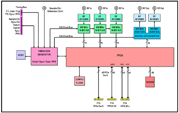
A/D converters, paired with the latest FPGA technology in an XMC form factor, provide a signal conversion and processing engine that can sample signals at extremely high data rates in a small package suitable for a small form factor recorder. These XMC modules serve as the recorder's front-end interface and are used to move multiple gigabytes per second of data through the system.

XMC modules are commonly available with A/D converters that have maximum sample rates ranging from 200 MS/s (2 million samples per second) to 6.4 GS/s (6.4 billion samples per second). The sample rate of the A/D converter dictates the maximum RF signal bandwidth that can be sampled and recorded. For example, a 200 MS/s A/D converter with an 80% anti-aliasing filter can record 80 MHz of signal bandwidth, while a 6.4 MS/s A/D converter with a similarly shaped filter can record over 2.5 GHz of signal bandwidth. Some applications require a very wide bandwidth signal to be captured, while others require the ability to capture several channels of narrower band signals, so it is important to provide an array of A/D converter offerings in an XMC form factor to support our SFF signal recorder.

While the A/D sample rate is important for selecting the front end of a recorder, the dynamic range of the A/D is equally important to effectively match each application's requirement. For an RF signal recorder, dynamic range can be described as the ratio between the largest and smallest signals that can be recorded successfully. Some signal acquisition scenarios require the ability to record very small signals in the presence of potentially very large signals, requiring an A/D converter with excellent dynamic range.

The bit resolution of the A/D converter and the effective number of bits (ENOB) help to express dynamic range to the user. However, A/D converter specifications like spur free dynamic range (SFDR) and signal to noise ratio (SNR) provide an even more useful way to present dynamic range.

High performance 200 MS/s A/D converters provide 16 bits of resolution and offer SFDR specifications greater than 85 dBFS and SNR specifications greater than 75 dBFS, while 6.4 MS/s A/D converters provide 12 bits of resolution and offer SFDR closer to 65 dBFS and SNR closer to 55 dBFS. Typically, the higher the sample rate of the A/D converter, the lower the dynamic range, so it is important to provide a wide array of A/D converters on XMC modules to cover different types of applications.

FPGAs coupled with A/D converters on XMC modules provide an excellent digital signal processing engine for the recorder. Digital downconverters, signal detection, radar gating, and acquisition time stamping are common processing capabilities that are often provided in standard FPGA IP designs. A well-developed set of FPGA IP modules greatly enhances the capabilities of an RF signal recorder.

D/A converters are often included on XMC modules to allow users to play back acquired signals or generate radar pulses. Multi-channel A/D and D/A XMC modules provide phase coherency across all channels. This is an essential capability of any real-time signal recorder.

Precision Time Stamping with Small GNNS Receivers

Extremely small Global Navigation Satellite System (GNNS) receivers have emerged over the last few years with support for Galileo, GPS, and Glonass systems. These small receivers support timestamping of acquired data with nanosecond precision. The receivers provide 10 MHz reference clocks and PPS signals to the recorder's XMC modules to allow users to capture the exact timing of gated or triggered events.

GNNS receivers also allow systems to record the latitude, longitude, and altitude of the recorder for logging flight paths, vehicle movement, or static ground location, if required. GNNS receivers often provide options for oven-controlled oscillators for operation across a wide range of temperatures and accelerometers to improve time and position accuracy during rapid acceleration, allowing them to operate in a wide range of environments.

Drive Packs Simplify High Capacity Data Storage

Streaming data to disk in real-time at rates in the gigabytes per second has been achievable in large rackmount recorders by striping data over a RAID array of many SSDs. High-performance RAID controllers not only provide lightning-fast write speeds but offer redundancy, protecting against the rare but disastrous disk failure that could occur during a mission. RAID controllers also utilize SSD features to provide data encryption and secure erase capabilities.

Another feature typically seen in rackmount recorders is front panel removable drives. An array of as many as 48 drives, mounted to sleds, can be inserted and removed individually from the front of the system. This allows users to remove all recorded data while allowing the recorder to remain mounted in a rack. It also allows users to maintain multiple sets of drive arrays to minimize downtime between missions.

The challenge of maintaining the features and performance of larger form factor recorders is facilitated by the growing solid state storage demand driven by data centers. V-NAND flash technology has enabled solid state drive capacity and write rates to continue to increase in very small package sizes. These inherent advances in solid state technology provide a path for shrinking the data storage array, allowing simpler and smaller designs with performance and features equal to those of far larger systems.

Small drive packs, containing an array of solid state devices, provide storage speed and capacity previously only available with many individually removable SSDs. By designing the packaging of a storage array into a drive pack, the job of managing a high drive-count system is replaced with the job of managing a single drive pack, providing a tremendous easeof-use benefit.

A single high-insertion-cycle connector designed into the drive pack provides a far more reliable mechanism for the removable storage media than the standard SATA connectors typically available in rackmount systems. Well-designed drive packs are capable of holding tens of terabytes of data and are capable of storage speeds in the gigabytes per second. Drive packs must be designed for easy removal while the recorder remains mounted in the vehicle or aircraft.

Pentek's QuickPac drive pack provides solid state storage in a small package
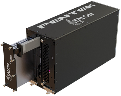
Figure 2. Pentek's QuickPac™ drive pack provides solid state storage in a small package. These pictures show the QuickPac drive pack and OS drive removed and partially ejected from the Talon Model RTX 2589 3.6 GS/sec Ultra Wideband RF/IF Extreme 1/2 ATR Recorder.

QuickPac drive pack and OS drive removed and partially ejected from the Talon Model RTX 2589 3.6 GS/sec Ultra Wideband RF/IF Extreme 1/2 ATR Recorder

Creative Thermal Management Techniques Allow for Operation in Harsh Environments

One of the issues in reducing the package size of the data storage media is maintaining a thermal environment that will allow the drive pack to perform at its highest level. Solid state memory controllers will throttle access speeds if the thermal environment is not properly managed. This issue is not only an important concern for the storage media but for all electronics in a SFF recorder. A set of A/Ds can draw 10 watts or more. FPGAs often draw 25 watts or more. CPUs typically draw between 35 and 90 watts. High performance RAID controllers often draw 15 to 25 watts. And drive packs can draw tens of watts. While efforts can be made to minimize power consumption, heat management is one of the most critical aspects of a recorder's design.

Many RF signal recorders are installed in aircraft pods, naval ships, or other outdoor environments with little or no protection from the environment. In order to operate in a wide array of environments it is important to protect all electronics from environmental elements such as water, humidity, sand, dust, and salt fog. A hermetically sealed chassis is desirable, but brings with it the issue of heat mitigation of internally mounted electronics.

Custom-designed heat sinks that provide conductive thermal paths to the walls of the recorder's chassis provides some relief, but chassis walls still require sufficient air flow to be effective. Plenums can be used to create air channels throughout the chassis to provide a more efficient cooling design. Custom heat sinks that are integrated into the plenum's walls provide an ultimate level of cooling by allowing air to be channeled directly through all of the electronics' heat sinks. This allows all system electronics to remain sealed from the outside environment while being adequately cooled.

Integrating a fan into the plenum helps assure air flows through the heat sinks, providing an excellent cooling solution. This is ideal for systems running in hot environments like an aircraft idling on the tarmac of an air base or a military vehicle running in the dessert. But what about cold environments, like an aircraft pod at high altitude or an unpressurized UAV flying in the arctic? It is equally important that our RF signal recorder is able to run at very cold temperatures.

One of the advantages of sealing all system electronics from the outside environment is that the electronics can selfheat more easily than if they were directly exposed to the cold environment. This self-heating process is compromised if a fan in the plenum tube is blowing cold air across heat sinks, so it is very important to provide control over this fan.

Integrated fan controllers should be provided to monitor the environment and switch fans off to allow for self-heating and then re-engage when components become hot. This balance between hot and cold is easily calibrated, ultimately providing a recording system that can operate at both temperature extremes. Note that while the measures described above for thermal management will help to provide an ideal environment for the recorder's electronics, it is important to use industrial-grade components whenever possible.

Pentek's Talon RTX SFF recorders provide a plenum tube that runs through the chassis
Inside the plenum tube, this shows the fan pulling cool air and pushing it across the heat sinks, providing conduction paths to all system electronics

Designing for Military Specifications and Compliance

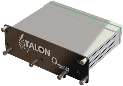
MIL-STD-810, Environmental Engineering Considerations and Laboratory Tests, is a United States military standard that emphasizes tailoring equipment's environmental design and test limits for the conditions that it will experience throughout its service life. The standard also establishes test chamber methods that replicate the effects of environments on the equipment rather than imitating the environments themselves.

MIL-STD-810 addresses a broad range of environmental conditions that include: low pressure for altitude testing; exposure to high and low temperatures plus temperature shock (both operating and in storage); rain (including windblown and freezing rain); humidity, fungus, salt fog for rust testing; sand and dust exposure; explosive atmosphere; leakage; acceleration; shock and transport shock; gunfire vibration; and random vibration. The standard describes environmental management and engineering processes that can be of enormous value to generate confidence in the environmental worthiness and overall durability of a system design. (Wikipedia, 2018)

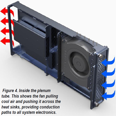
While operating environments vary greatly, meeting as many criteria in the MIL-STD-810 specification as possible is imperative to providing a reliable and robust product. Anodized metal with form-in-place gaskets allows for sealed protection against rain, humidity, fungus, salt fog, and sand and dust exposure. CAD software provides simulation analysis tools to assist with thermal design and structural integrity. Well-executed design techniques help assure a smooth laboratory testing process.

MIL-STD-461 is another popular military specification requirement for RF signal recorders. MIL-STD-461 provides the requirements for the control of electromagnetic interference (EMI) emissions and susceptibility characteristics of electronic, electrical, and electromechanical equipment and subsystems designed or procured for use by activities and agencies of the Department of Defense (DoD). (NTS, 2018)

A Talon RTX Extreme 1/2 ATR Recorder signal recorder being tested to MIL-STD-461
Figure 5. A Talon RTX Extreme 1/2 ATR Recorder signal recorder being tested to MIL-STD-461


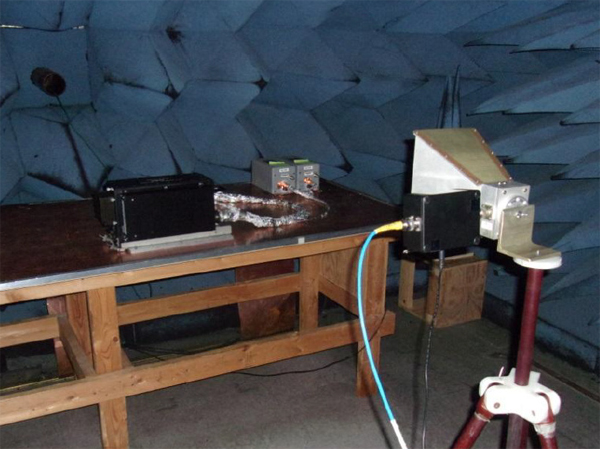
RF test laboratories use anechoic chambers to run a series of MIL-STD-461 tests that include radiated emissions, radiated susceptibility, conducted emissions, and conducted susceptibility for a range of frequencies. It is typical to cover a radiated range up to 18 GHz and a conducted range up to 10 MHz on power leads.

It is important to take the appropriate design steps to meet MIL-STD-461 compliance since iterative independent laboratory testing becomes very expensive. Design techniques used to control EMI include the use of RF emission filters and RF gaskets to prevent radiated electromagnetic emission and susceptibility. Additionally, an in-line EMI power filter designed for the internal power supply can be used to protect against conducted emission and susceptibility.

Why the Obsession with SWaP?

The term SWaP has become a commonly used buzzword to describe the requirement for electronic systems that are small in size, weight, and power consumption. Why the obsession with SWaP? A lot of it has to do with sophisticated electronics small enough for unmanned vehicles. Another is placing computer power, displays, communications, and sensors on an already overburdened infantryman. Overall, today's focus on small, lightweight electronic systems that don't use much power has to do with bringing as much capability to the forward edge of battle as possible. (Keller, 2013)

While we have already focused on reducing the size of our RF signal recorder, designing for weight and power reduction require additional strategies. The good news is that weight and power have a direct relationship in that the lower the power consumption, the less heat dissipated by the system. Removal of heat from the system's electronics via conduction requires conductive materials such as aluminum or copper. While copper is more effective for conducting heat, its density is far greater than aluminum, adding undesirable extra weight to the recorder.

In order to design for reduced weight we must minimize the power consumption of the system and use lightweight materials like aluminum with efficient thermal paths to the cooling channels designed into the system. High-speed recording systems often do not require a tremendous amount of processing power. Since hardware DMA controllers are used to move data to disk, processors are often used to simply "manage" the data flow. Intel's latest i7 processors are now offered in versions with lower clock rates and power consumption. An eighth generation i7, clocking at 2.4 GHz, limits power consumption to 35 watts and can be configured to draw as little as 25 watts.

Furthermore, efficient FPGA designs allow digital signal processing to reside in smaller, more efficient FPGAs. Xilinx's Kintex Ultrascale family offers excellent performance with significant power reduction over previous-generation FPGAs. Component selection and an efficient design help to control the power consumption and dissipation of the recorder, allowing us to use less material for heat sinking and reduce the total weight of the package.

Ease-of-Use Considerations

While SWaP factors are important design considerations during the development of a SFF RF signal recorder, it is equally important that the system is designed to be easy to use from both a hardware and software standpoint. Designing a system in a standard form factor helps to simplify the installation process by providing familiar mounting mechanisms in a common and proven footprint. ARINC 404 is an aeronautical standard that specifies mechanical dimensions of line replaceable units (LRUs) and their racking systems in aircraft. ARINC 404 specifies dimensions for several sizes of ATRs (Air Transport Racks), providing us with a choice of standard footprints for a signal recorder.

It is important to design a system that can be installed in an aircraft or vehicle in a permanent fashion but still provide accessibility to the user. Easy-to-swap modular components like fans, drives, and other parts of non-volatile memory within the recorder allows the system to be serviced and sanitized of classified or otherwise sensitive data easily. All removable components should be accessible via the front panel of the system using captive hardware without the requirement of special tools.

Software should include a straightforward and simple Application Programming Interface (API) to control the system as well as a suite of RF signal analysis tools to allow users to instantly analyze recorded data. RF signal recorders typically provide a gigabit Ethernet interface for control of the unit from an external computer. This interface can also be used to stream data to allow users to monitor RF signals prior to, during, and after recording signals.

It is essential to be able to remotely control the recorder to allow it to operate in unmanned environments. These environments often require the user to create a custom control interface, making the API an important part of the recorder. It is also desirable to provide a fully functional graphical user interface (GUI) to allow users to operate the system immediately out of the box. The GUI should also be able to run remotely.

Applications for SFF RF Signal Recording

RF signal recording is a critical component of any radar, signal intelligence, beamforming, or electronic warfare system. A well-designed system provides excellent RF signal acquisition hardware that is small, lightweight, low-power, and capable of operating in a wide range of operating environments. Features such as drive packs and other serviceable modular components make an RF signal recorder easy to install and maintain in tight spaces, allowing ultra-wide bandwidth RF signal recording to reside in places never before possible.

Ultra-wide bandwidth RF signal recorders have allowed engineers to capture large swaths of the RF spectrum necessary for wide bandwidth radar systems and improved SIGINT capabilities. While real-time recording of a gigahertz or more of RF bandwidth is commonly available in 19-inch rack-mountable systems, shrinking this capability into a form factor suitable for UAVs, aircraft pods, or other confined spaces has proven challenging for the industry. Small, rugged packages must be capable of operating in extreme environments while providing storage capacities and data streaming throughputs similar to those offered by larger systems.

The back of Talon RTX Model 2586 200 MS/sec RF/IF Extreme 1/2 ATR recorder
Figure 6. The back of Talon RTX Model 2586 200 MS/sec RF/IF Extreme 1/2 ATR recorder

The front of the Talon RTX Model 2586 where the system fan, operating system SSD and QuickPac drive pack are easily accessible
Figure 7. The front of the Talon RTX Model 2586 where the system fan, operating system SSD and QuickPac drive pack are easily accessible

The Talon RTX Model 2586 recorder's rear panel connectors
Figure 8. The Talon RTX Model 2586 recorder's rear panel connectors

Bringing it all Together

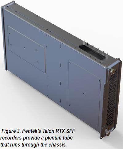
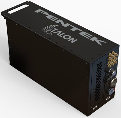
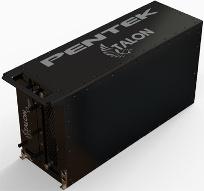
Designed using the techniques described in this article, Pentek offers the Talon RTX SFF product line. Figures 6, 7, and 8 present different views of the Talon RTX SFF recorder.

All Talon RTX SFF Recorders include the Pentek SystemFlow® recording software. SystemFlow features a Windows based GUI that provides a simple means to configure and control the recorder. SystemFlow includes signal viewing and analysis tools, that allow the user to monitor input signals prior to, during, and after a recording session. These tools include a virtual oscilloscope, a spectrum analyzer and spectrogram displays.

References


CONNECT ON SOCIAL:  Follow Us On Facebook Follow Us On LinkedIn Follow Us On Twitter Follow Us On YouTube

Pentek, Inc. • One Park Way, Upper Saddle River, NJ, 07458, USA
Tel: +1 (201) 818-5900 • Fax: +1 (201) 818-5904 • Map + Directions • Site Map
Terms of Use • Privacy Policy • Copyright © 2024 Pentek, Inc. All Rights Reserved.