| Home > Tutorials > The Many Advantages of Optical Links |

Advances in optical interface technology boost performance levels to help meet increasing data rates and signal bandwidths. New specifications define how to deploy these optical links within open industry standards, affording improved interoperability and supporting future upgrades. Offering many advantages over traditional copper connections, optical links will boost data rates, improve signal integrity and security, and greatly extend distance between system components.
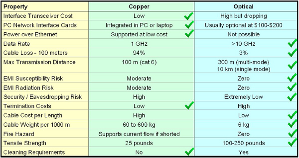
One major shortcoming of copper cable is signal loss, which becomes a serious limitation for higher frequency signals and longer cable lengths. Across a span of 100 meters, optical cables can sustain data rates up to 100 times higher than copper cable.
Because copper cables radiate electromagnetic energy, eavesdropping on network cables is a major security concern, not only for military and government customers, but also for corporations, banks, and financial institutions. Advanced signal sniffers in vehicles and briefcases are hard to detect and restrict. Optical cables are extremely difficult to "tap" without damaging the cable, resulting in immediate detection.
Signals flowing in copper cables are also susceptible to contamination from nearby sources of electromagnetic radiation, such as antennas, generators, and motors. This is critical for military and commercial aircraft and ships, as well as manned or unmanned vehicles, which are often packed with dozens of different electronic payloads. Optical cables are completely immune to EMI and even lightning discharges.
Physically, optical cables are much smaller and lighter than copper cables, especially important for weight-sensitive applications such as weapons, unmanned vehicles, and aircraft. Optical cables will operate just as well when submerged in seawater, and are completely immune to electrical shorting—especially important where explosive vapors may be present. To ease installation through conduits and passages, optical cables have smaller diameters and can withstand up to ten times more pulling tension than copper cables.
Driven by huge commercial markets for data servers, storage networks, telecom systems, and home and office internet and entertainment systems, optical interfaces are replacing older copper connections for good reasons: cost and performance.
As the use of optical cables becomes more widespread, the cost per length can be much lower than copper cables that depend on commodity metal pricing. As is often the case, industrial, military and government embedded systems are now taking advantage of the many benefits of this rapidly advancing commercial technology.
An optical cable is a waveguide for propagating light through an optical fibre. It consists of a central core clad with a dielectric material having a higher index of refraction than the core to ensure total internal reflection. Optical cables use either multi-mode or single-mode transmission.
Multi-mode cables accept light rays entering the core within a certain angle of the axis. They travel down the cable by repeatedly reflecting off the dielectric boundary between the core and the cladding. The core diameters are typically 50 or 62.5 microns, and the wavelength of light is typically 850 nm.
Single-mode cables propagate light as an electromagnetic wave operating in a single transverse mode straight down the fibre using typical wavelengths of 1310 and 1550 nm. The core diameter must be no greater than ten times the light wavelength, typically 8 to 10 microns. Although single-mode cables can carry signals over lengths 10 to 100 times longer than multimode, the transceivers are more expensive.
Hundreds of different types of optical cable connectors exist, each addressing specific applications and environments. The challenge is connecting the ends of two optical cables to retain the maximum fidelity of the light interface, in spite of human factors, tolerances, contamination, and environments. Special tools and kits for cleaning the ends of each optical fibre are essential for reliable operation.
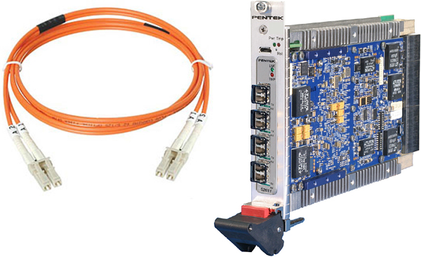
Coupling electrical signals to light signals for transmission through optical cables requires optical transceivers. Most systems require full duplex operation for each optical link to support flow control and error correction. A pair of optical fibers, often bonded together in the same cable, supports transmit and receive data flowing in opposite directions.
Although several analog light modulation schemes (including AM and FM) have been used in the past, now almost all transceivers use digital modulation. Optical emitters simply translate the digital logic levels into on/off modulation of the laser light beam, while the detectors convert the modulated light back into digital signals. This physical layer interface for transporting 1's and 0's can support any protocol.
The latest transceivers use laser emitters to support data rates to 100 Gbits/sec and higher, and each generation steadily reduces the power, size and cost of devices. Different technologies are required for emitters and detectors, but both are often combined in a single product to provide full-duplex operation.
Optical transceivers thus provide a physical layer interface between optical cables and the vast array of electrical multi-gigabit serial ports found on processors, FPGAs, and network adapters. As a result, optical transceivers are transparent to the protocols they support, making them appropriate for a virtually any highspeed serial digital link.
Electrical signals of the optical transceivers connect to the end point device, which must then handle clock encoding and recovery, synchronization, and line balance at the physical layer. Data link layer circuitry establishes framing so that data words can be sent and received across the channel.
Protocols define the rules and features supported by each type of system link, ranging from simple transmission of raw data to sophisticated multi-processor support for distributed networks, intelligent routing, and robust error correction. Of course, heavier protocols invariably mean less efficient data transfers and increased latency. Generally, it is best to use the simplest protocol that satisfies the given system requirement.
As an example of a lightweight protocol, Aurora for Xilinx FPGAs features onboard link-layer engines and high-speed serial transceivers. Aurora is intended primarily for point-to-point connectivity for sending data between two FPGAs. It includes 8b/10b or 64b/66b channel coding to balance the transmission channel, and supports single- or full-duplex operation. Aurora handles virtually any word length and allows multiple serial lanes to be bonded into a single logical channel, aggregating single lane bit rates for higher data throughput. Data rates for each serial lane can be 12.5 Gbits/sec or higher. Extremely simple and with minimal overhead, Aurora is very efficient in linking data streams between multiple FPGAs within a module, or between modules across a backplane.
Stepping up in complexity is the Serial FPDP protocol defined under VITA 17.1. It addresses several important needs of embedded systems, including flow control to avoid data overruns, and copy mode to allow one node to receive data and also forward it on to another node. The copy/loop mode supports a ring of multiple nodes eventually completing a closed loop. The nominal data rate on each lane is 2.5 Gb/s, but advances in device technology now support rates almost twice that speed.
Infiniband defines a flexible, lowlatency, point-to-point interconnect fabric for data storage and servers with current rates of 14 Gbits/sec, moving up to 50 Gbits/sec in the next few years. Channel speeds can be boosted by forming logical channels by bonding 4 or 12 lanes.
The venerable Ethernet protocol still dominates computer networks, with 10 GbE now commonly supported by a vast range of computers, switches, and adapters. Even though Ethernet suffers from high overhead, making it somewhat cumbersome for high-data-rate, low latency applications, its ubiquitous presence virtually assures compatibility.
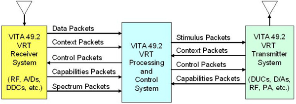
Approved as an ANSI standard in 2007, VITA 49.0 defines standardized packets for connecting software radio systems for communications, radar, telemetry, direction finding, and other applications. The original specification addressed only receiver functions. Receive signal data packets deliver digitized payload data, a precise time stamp, and identifiers for each channel and signal. Context packets include operating parameters of the receiver including tuning frequency, bandwidth, sampling rate, gain, antenna orientation, speed, heading, etc. One notable shortcoming of the original specification was its inability to control the receiver.
VITA 49.2, a new extension to VRT now in balloting, adds control packets for delivering operational parameters to all aspects of the radio equipment, as well as support for transmitters. The new stimulus packets contain streaming digital samples of signals to be transmitted. Other new packets, called capabilities packets, inform the host control system of the available hardware in the radio along with the allowed range of parameters for control. Lastly, spectrum packets from the receiver deliver spectral information to help simplify spectral survey and energy detection operations required by the control system.
With this latest extension, VRT provides a standardized protocol for controlling and configuring all aspects of a software radio transceiver. One major objective is enabling a common radio hardware platform to handle a wide range of applications simply by implementing new host software algorithms that exploit VRT protocols to achieve the required modes of operation.
Although optical interfaces using various connectors and cable types have been deployed in embedded systems for years, most of them use front panel connections. This can be a maintenance issue and is often not permitted in conduction-cooled systems.
The VITA 66 Fiber Optic Interconnect group has developed a set of standards that bridge optical connections directly through the VPX backplane connector. The first three are variants for 3U and 6U systems and are based on MT, ARINC 801 Termini, and Mini-Expanded Beam optical connector technology, respectively.
The metal housings are physically dimensioned to replace one or more of the standard MultiGig RT-2 VPX bladed copper connectors. The high-density MT variant defined in VITA 66.1 provides the highest density of the three, with up to 12 or 24 pairs of optical fibers, while VITA 66.2 and 66.3 each provide 2 pairs.
A fourth standard soon to be released, VITA 66.4, uses the MT ferrule but with a metal housing half the size of VITA 66.1, thus occupying only half of the 3U VPX P2 connector position. These housings are available from major vendors, including TE Connectivity and Molex.
To simplify implementation, Samtec offers its FireFly™ Micro Fly-Over system. It consists of a 12 pairs of optical fibres installed in an MT ferrule. One 12-lane optical flat cable connects to a small VCSEL laser emitter module and the other connects to a detector module.
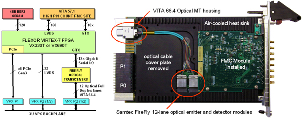
Figure 3 shows the industry's first implementation of the emerging VITA 66.4 standard, the Pentek Flexor® Model 5973 3U VPX Virtex-7 FMC carrier. Here the electrical interfaces of the FireFly emitter and detector modules are connected directly to the GTX serial transceiver pins of the Virtex-7 FPGA. Today, FireFly transceivers are rated for 14 Gbits/sec with 28 Gbits/sec versions coming soon. With Pentek's Model 5973 operating at nominal data rates of 10 Gbits/sec through each optical fibre using the Aurora protocol, the backplane throughput is 12 GB/sec, simultaneously in both directions.
The first version of this product uses multi-mode transceivers and cable to support cable lengths of 100 meters or more. Single-mode transceivers will extend the distance to several kilometers. A wide range of MT optical cables and connector products allow board-to-board connections across the backplane, and backplaneto-chassis connections for external MTP cables to remotely located systems.
The 12 GB/sec VITA 66.4 optical interface complements the 8 GB/sec Gen 3 x8 copper PCIe interface on VPX P1, offering plenty of I/O for demanding applications. System engineers can now choose between optical and copper links to solve high data rate connectively requirements and take advantage of the benefits of each technology.
| CONNECT ON SOCIAL: |
|
|
|
|