| Home > Tutorials > Small Form-Factor Strategies for Embedded Systems |

The proliferation of unmanned military vehicles tasked with critical communications and radar requirements drives the need for powerful data acquisition and signal processing products that must fit into increasingly tighter spaces. New industry standards meeting these needs offer smaller circuit boards and enclosures, optical gigabit serial links, and advanced thermal management strategies. With new resources found in the latest processors and FPGAs, system designers can now create powerful, compact systems surpassing performance levels achievable only a few years ago.
The VITA and PICMG organizations actively promote and maintain standards for embedded systems suitable for commercial and military applications. Consisting of interested members from industry, academic and government organizations, each working group contributes towards the development of a new standard.
Once adopted and put into practice, refinements and extensions to these standards ensure the long life cycle support required for most government programs. Customer acceptance of a new standard fosters an open community of vendors offering compatible products compliant with the standards. Competitive market forces help keep costs down, encouraging customers to request new systems based on successful standards.
Five new small form-factor standards for embedded system modules and backplanes are currently in draft or trial use status awaiting final adoption. While each of these standards offers unique mechanical features, all of them are derivatives of existing embedded system standards. They all combine the most appropriate aspects of proven designs and leverage new technology to help reduce size, weight, power and cost (SWaP-C).
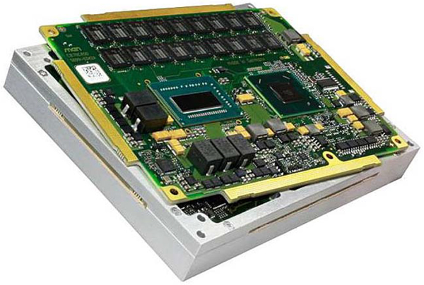
VITA 59 – Rugged COM Express: The PICMG COM Express standard defines a series of modules (cards) and backplanes supporting processors, memory, networks, and specialized I/O. VITA 59 extends COM Express for use in harsh environments of extended temperature, shock and vibration. As shown in Figure 1, this is accomplished through relatively simple mechanical modifications to the printed circuit board of the module, leaving the central PCB design largely intact.
This strategy allows developers to create two similar versions of each module, one for commercial, and one for rugged applications. Software and firmware can be developed on the commercial platform and then later deployed without changes in a fully ruggedized system.
VITA 73 – Rugged Small Form Factor: Based on the electrical specifications of VPX (VITA 46 and 48), VITA 73 aims to shrink the modules and chassis as much as possible, while maintaining full system-level performance in rugged environments. Definitions for single- and doublewide modules, both 101.5 mm deep and 71 mm across, include a variety of backplane pin configurations supporting various module functions.
These include power supplies, CPUs, 2.5 in. disk drives, and payload functions such as digital and analog I/O. The backplane uses different types of pin/socket connectors for power, SATA, analog I/O, and data. Gigabit serial data pins are rated to 10 Gb/sec to handle the latest versions of popular serial standards.
VITA 74 – System Small-Form Factor Module: Like the VITA 73 specification, VITA 74 embraces all of the VITA 46 VPX electrical signal definitions for two sizes of small form-factor modules. Both are 89 mm deep and 75 mm across, with a width of either 12.68 or 19 mm. The modules connect to the backplane using the same connectors defined in VITA 57 for FMC modules and carriers, with 200 or 400 contacts, depending on the module width. Unlike VITA 73, these same connectors handle all power and signal connections to the modules.
The gigabit serial pins support rates up to at least 8 Gb/sec to support PCIe Gen. 3 interfaces commonly found in embedded platforms. VITA 74 defines a comprehensive IMPI (intelligent platform management interface) using the I2C management bus that maintains and monitors system components and the identities of FRUs (field replaceable units).
VITA 75 – Rugged Small Form Factor: Unlike the other standards, VITA 75 addresses SWaP-C challenges by defining characteristics for the system chassis, saving the details of module size and internal connectors for later extensions. VITA 75 stresses the importance of thermal management packaging techniques to place hot components as close as possible to the cold plate or chassis walls. VITA 75 proposes two types of modules: stacked and bladed. Stacked modules use a male connector on one side of the PCB and a female on the opposite side, so that adjacent modules can be joined by pressing them together. Bladed modules are joined by a backplane with connectors similar to those on VITA 46.
VITA 75 defines many different types of rugged embedded system enclosures through numerous profiles for size, mounting and cooling options. Profiles for circular military connectors to handle power, signals, networks, and other interfaces follow a welldefined nomenclature inspired by VITA 65. Likewise, numerous front panel profiles define various combinations of connectors to meet requirements for a wide range of chassis sizes and system I/O requirements.
PICMG Rugged MicroTCA: PICMG Specification 3.x defined ATCA (Advanced Telecommunication Computing Architecture) boards, backplanes and chassis for the latest generation of commercial communications equipment. AMCs (Advanced Mezzanine Cards) are daughter-cards that attach to the main ATCA carrier boards. Widespread adoption of ATCA for high-volume commercial markets helps keep product prices lower than equivalent functions from traditional COTS vendors.
The MicroTCA specification converts AMCs to modules that can be plugged into a small form-factor chassis with a backplane. Its well defined backplane topology using gigabit serial interconnections and platform management strategies, presents a very capable architecture for high-performance embedded systems for government and military applications in benign environments.
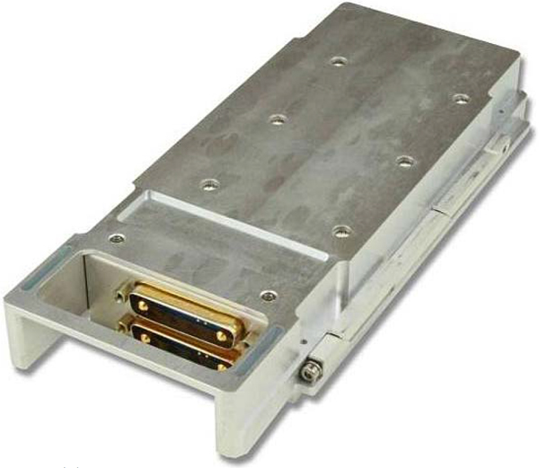
As shown in Figure 2, Rugged MicroTCA extends these systems for deployment in harsh environments of temperature, shock, vibration, humidity, etc. Specified limits proven in qualification tests of the latest versions of Rugged MicroTCA meet or exceed those of VPX. As a result, vendors of Rugged MicroTCA are now securing design wins for ruggedized military system programs.
Gigabit Serial Interfaces: A common theme pervades all five of these new standards: the use of gigabit serial interconnects to eliminate the parallel bus backplanes of previous generation systems like VMEbus and CompactPCI. Virtually all consumer, commercial, industrial, and military applications have enjoyed widespread adoption of these gigabit serial standards including Gigabit Ethernet (GbE), PCI Express (PCIe), SATA, SerialRapidIO (SRIO), and others.
A single gigabit serial link can deliver high-speed data over a single differential pair at rates to 10 Gb/sec, or more. This reduces the circuit board area and the number of connector pins required to sustain a given data transfer rate.
FPGAs: FPGAs offer designers more ways to achieve smaller form factors than virtually any other device. Built-in gigabit serial interfaces and standard protocol engines for PCIe and GbE eliminate the need for additional interface chips. Custom protocol requirements, like SerialFPDP, can be configured using internal FPGA resources. This technique extends easily to simpler tasks such as custom data formatting, buffering and packetizing.
Configurable I/O ports on FPGAs handle direct connections to specialized peripheral interfaces for exotic sensors and transducers, like a 48-bit interface to a 3.6 GHz 12-bit A/D, for example. Timing, gating, triggering, and synchronization structures for critical applications like phased-array radars take advantage of configurable logic, state machines, and counters, all inside the FPGA.
FPGAs also feature built-in advanced SDRAM controllers for direct connection to external DDR3 memory chips, essential for transient capture of radar pulses, digital delay lines and signal-processing workspace. Sophisticated circuitry automatically trains the memory timing signals for optimum performance at power up.
Front-end digital signal-processing requirements, like digital downconverters for software radios, are perfect candidates for the many DSP engines found on most FPGAs. The largest Virtex-7 device now contains 3600 DSP48E engines, vastly outstripping the raw processing power of DSPs and GPPs. This type of preprocessing can deliver two-fold savings: lower output data rates and simpler downstream processing engines.
These benefits result in smaller circuit boards, fewer components, and simpler connections. At the same time, power dissipation for a given function within a Virtex-7 FPGA has dropped by one-half compared to the previous Virtex-6 generation. This eases thermal management and extends missions for battery-operated or powersensitive applications.
Backplane Optical Interfaces: Initiatives by standards organizations for optical interconnections are now yielding product offerings. Approved standards from the VITA 66 Fiber Optic-Interconnect group define three backplane optical interfaces for 3U and 6U VPX; these are variants based on MT, ARINC 801 Termini, and Mini-Expanded Beam optical technology, respectively. All of them support single- or multi-mode fiber interfaces by replacing one or more of the standard VPX-bladed connectors. Blindmate connectors between the VPX module and the backplane feature spring-loaded inserts containing optical cable assemblies that float within metal housings. Alignment pins and holes in each half of the mating assemblies ensure exact alignment of the polished ends of each optical path. The MT variant in VITA 66.1 provides the highest density with up to 24 pairs of optical fibers, while VITA 66.2 and 66.3 both provide two pairs.
The unreleased VITA 66.4 standard based on the high-density MT ferrule uses a halfsize metal housing for a smaller module and backplane footprint. It supports either 12 or 24 pairs of optical cable. First versions of the connectors are already available from major vendors, including TE Connectivity and Molex.
To ease implementation of the optical interface, Samtec is now sampling its FireFlyTM Micro Fly-Over system. This small module interfaces 12 lanes of gigabit serial electrical signals to laser transmitters and receivers connected through 12-lane optical flat ribbon cables and terminated in an MT ferrule.
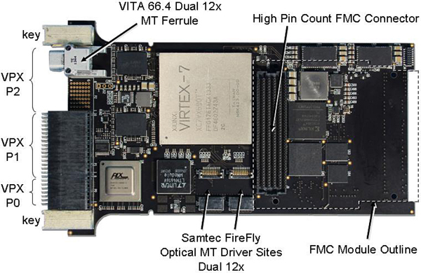
Figure 3 shows the Pentek Flexor® Model 5973 3U OpenVPX carrier for FMC illustrating these small form-factor enabling technologies including PCIe Gen. 3 system interface, the Virtex-7 FPGA, and the first implementation of the proposed VITA 66.4.
Optical interfaces benefit small form-factor systems in many different ways. Optical cables are lightweight, smaller diameter alternatives to copper cables, especially important in unmanned vehicles sensitive to weight and packed tightly with electronic payloads. They are completely immune to electromagnetic susceptibility or emissions for added reliability in electrically noisy environments such as antenna masts and engine rooms, and for added security against eavesdropping.
Optical cables can transport existing gigabit serial traffic at rates beyond 10 Gb/sec, extending these interfaces between modules, chassis and racks. Depending on the optical fiber mode, these links can extend from 100 meters to several kilometers, easily covering the length of the largest aircraft and surface vessels. Remote sensors and data acquisition pods in small enclosures can be mounted close to antennas, sending digitized signals back to a central processing center across optical links.
With so many proposed approaches to small form-factor embedded systems, engineers need to determine which technical aspects of each approach are most important for a particular application and carefully consider the companies backing each standard. It is highly likely that no single standard will emerge as the winner.
However, system designers waiting for a final outcome will miss out on the significant, tangible benefits available today. New extensions to these standards will be inspired by customer-driven opportunities, helping steer the technology with real-world requirements.
| CONNECT ON SOCIAL: |
|
|
|
|