| Home > Pipeline Newsletters > NeXtRAD Multistatic Radar System |

| |||||||||||
|
Spring 2017 Vol. 26, No. 2 | |||||||||||
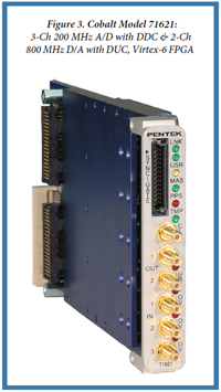
A Pentek Transceiver Provides the SDR Interface for the NeXtRAD Multistatic Radar Systemby Dane Du PlessisNeXtRAD is a dual-band, dual-polarization, multistatic radar system under development at the University of Cape Town (UCT) in collaboration with University College London (UCL). The primary mission of the system is to collect multistatic data of small radar cross-section maritime targets embedded in sea clutter. 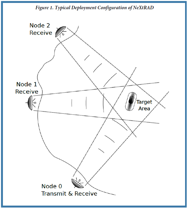 NeXtRAD is a multi-sensor network comprised of three stations (or nodes) separated by several hundred meters, all focussing on a common target area as shown in Figure 1. Only node 0 generates and receives radar signals, while nodes 1 and 2 are receive only. The system requires a usable bandwidth of 50 MHz to achieve a range resolution of three meters. Each node has dual-polarized L- and X-band antennas (IEEE definition) with a 10-degree beamwidth. This arrangement effectively forms a pair of bistatic radars in combination with a monostatic radar, which means that target data can be simultaneously acquired from three perspectives. This topology has advantages over single-sensor radars. NeXtRAD is a more capable version of NetRAD, a single-frequency multistatic radar developed by UCT and UCL. During the early stages of the NeXtRAD project, Pentek's Cobalt® Model 71621 transceiver system was identified as a suitable software-defined radio interface for the system. This article presents the early stages of the development of NeXtRAD, which uses Pentek's Model 71621 module as the digital transceiver of the system in a monostatic configuration. NeXtRAD System Overview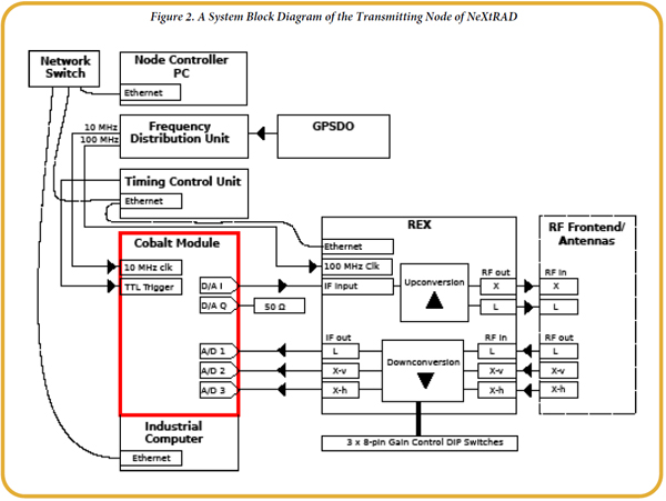 The active node of the NeXtrad multistatic system consists of the following (see Figure 2):
The Cobalt module can be configured to accept the 10 MHz signal from its front panel SSMC clock input. The GPSDO also supplies a trigger pulse which precisely synchronises the start of a radar measurement. After an initial trigger event from the GPSDO, the TCU takes over and delivers the trigger pulse to the Cobalt module at the pulse repetition frequency (PRF). Signal PlanningThe transmitted pulse is generated by the Cobalt module in the active node of the sensor network. The system employs linear frequency-modulated pulses with 50 MHz bandwidth and duration of 1 to 10 micro seconds, at a PRF from 1 to 2 kHz. The Cobalt module is able to supply the 50 MHz bandwidth signal on a 125 MHz intermediate frequency (IF) at a 720 MHz output frequency from one of its two available 16-bit D/A output channels. The REX upconverts the IF waveform to either L- or X-band. After amplification, the waveform is transmitted via the appropriate antenna to illuminate the target area with either vertical or horizontal polarization.
The phase of the digital sine and cosine terms generated in the DUC and DDC can be reset to zero on rising edges of the external trigger with proper configuration of the control registers for the DAC5688 and the DDC IP core. This ensures that phase offsets introduced to the radar signal on generation or digitization can be ignored in post-processing as they do not vary between pulse repetition intervals. Initial Testing and ResultsThe controller software for the Cobalt module was developed using Pentek's ReadyFlow® software libraries, in conjunction with an arbitrary waveform generator, spectrum analyzer, and an oscilloscope. The digitization and waveform generation chains were developed and tested in separate controller programs before fusing these programs into a working source. A simple IF loop-back test using one of the D/A output channels and a signal splitter was sufficient do most of the development required for the digital transceiver before introducing the REX and other subsystems. 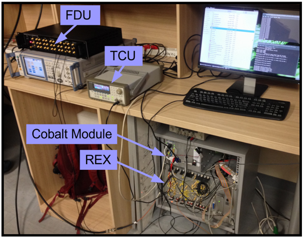 Figure 4. The hardware testing setup for the low-power prototype. Labeled are the frequency distribution unit (FDU), the timing control unit (TCU), the Cobalt module, and the receiver exciter (REX) The hardware configuration shown in Figure 4 was used to test a low-power (<24dBm transmit power) bench-top prototype of the active node, using an AWG to supply a rising-edge trigger to the Cobalt module and signal generators to supply synchronized reference signals to the REX and the Cobalt module. 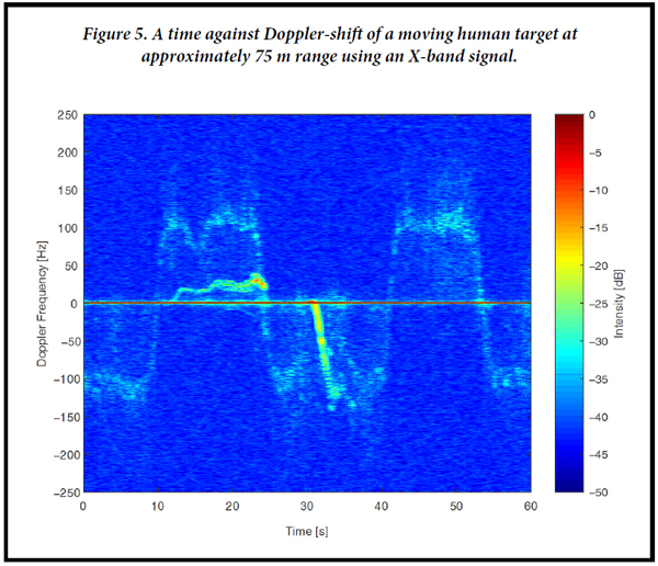 Using this system, it was possible to detect moving targets by their Doppler shift at close range, as shown in Figure 5. This data shows the doppler shift of a moving human target at approximately 75 meters from the transmitter, using a 0.5 micro second duration pulse with 50 MHz of bandwidth. Radial target velocity v and Doppler shift are related by the equation v=c/2(Fd/Fc)
where c is the speed of light, Fd is the Doppler shift, and Fc is the carrier frequency. With Fc = 8.5GHz (X-band) and Fd = 100 Hz at t=5s in the graph of Figure 5, the target is inbound at approximately 1.7 m/s. The large object seen moving from approximately 10 to 22 seconds and then from 30 to 32 seconds was a car backing out of a parking bay and driving away. Passive nodes are essentially identical to the active node, except for the transmitters which are not needed. Using virtually the same controlling software for the Cobalt module in the active node, passive nodes can record waveforms at precisely the same moment as in the active node. SummaryThe initial testing of the Cobalt module in the active node of the system demonstrated that the Pentek Model 71621 was well-suited to a pulse-Doppler radar application. With the required additional hardware, the passive nodes can be introduced to the network with minor alterations to code for the active node's digital transceiver. Overall, the Cobalt module met our requirements for phase stability and bandwidth, and it was easily integrated with the existing receiver exciter for the active node. The author would like to thank the following organizations for their generous financial support of the NeXtRAD project: ONR Global, the IET for the AF Harvey Research Prize, the South African National Defence Force, and the National Research Foundation of South Africa.
| |||||||||||
 |
| CONNECT ON SOCIAL: |
|
|
|
|