|
Model 6890 Clock, Synchronization and Gate Distribution VME Board
With up to 2.2 GHz clock, the new Model 6890 supports the Model 6826 A/D Converter Board
Features
- Synchronizes up to eight separate boards
- Synchronizes sampling and data acquisition for multichannel systems
- Synchronizes gating and triggering functions
- Clock rates from 800 MHz to 2.2 GHz
- Front panel SMA connectors for clock input and outputs
- Front panel MMCX connectors for gate/trigger and sync signal inputs and outputs
- Single-slot 6U VME board
| |
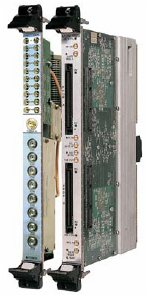
Model 6890 Sync & Gate
Distribution board (left) shown with
Model 6826 2 GHz A/D Converter
|
General Information
Model 6890 Clock, Sync and Gate Distribution Board synchronizes multiple Pentek I/O boards within a system. It enables synchronous sampling and timing for a wide range of multichannel high-speed data acquisition, DSP and software radio applications. Up to eight boards can be synchronized using the 6890, each receiving a common clock of up to 2.2 GHz along with timing signals that can be used for synchronizing, triggering and gating functions.
Input Signals
Model 6890 provides three front panel connectors to accept input signals. One SMA connector is provided for clock signal input, one MMCX connector accepts gate or trigger signals, and another MMCX connector is provided for synchronization. Two additional MMCX connectors are provided for Gate and Sync Enable.
Clock signals are applied from an external source such as a high performance sine wave generator. Gate and sync signals can come from an external source, or from one supported board set to act as the master.
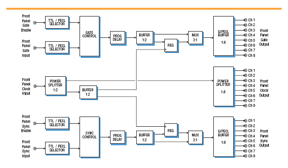
Clock Signals
The 6890 accepts clock input at +10 dBm to +14 dBm with a frequency range from 800 MHz to 2.2 GHz and uses a 1:2 power splitter to distribute the clock. The first output of this power splitter sends the clock signal to a 1:8 splitter for distribution to up to eight boards using SMA connectors.
The second output of the 1:2 power splitter feeds a 1:2 buffer which distributes the clock signal to both the gate and synchronization circuits.
Gate and Synchronization Signals
The 6890 features separate inputs for gate/trigger and sync signals with userselectable polarity. Each of these inputs can be TTL or LVPECL. Separate Gate Enable and Sync Enable MMCX inputs allow the user to enable or disable these circuits using an external signal.
A programmable delay allows the user to make timing adjustments on the gate and sync signals before they are sent to an LVPECL buffer. A bank of eight MMCX connectors at the output of each buffer delivers signals to up to eight boards.
A 2:1 multiplexer in each circuit allows the gate/trigger and sync signals to be registered with the input clock signal before output, if desired.
Accessories
Model 2890 provides various cable sets with options -002 through -008 supporting synchronization of two to eight boards. Options for individual cables are also available under Model 2890.
Supported Products
The 6890 currently supports the Model 6826 Dual 2 GHz, 10-bit A/D Converter VME Board. Contact the factory for an upto-date list of supported boards and modules.
For more information and a price quotation on the Model 6890, click here.
For more information and a price quotation on the Model 6826, click here.
|