|
Spring 2008 Vol. 17, No. 1
The Unmanned Aerial Vehicle Synthetic Aperture Radar System
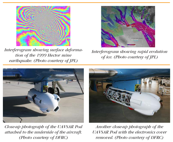
NASA’s Jet Propulsion Laboratory has built a reconfigurable L-band synthetic aperture radar (SAR), specifically designed to acquire airborne repeat-track SAR data for differential interferometric measurements. Differential interferometry can provide key deformation measurements, important for studies of earthquakes, volcanic eruptions and other dynamically changing geophysical phenomena.
Project Objectives
Earth science research often requires crustal deformation measurements at a variety of time scales from seconds to decades. To this end, the NASA Solid Earth Science Working Group has recommended an observational program that includes both airborne and spaceborne capabilities. Since many geophysical processes, such as volcanic eruptions and earthquakes, occur quickly and require immediate response, the program goal is to provide Earth deformation measurements on an hourly basis with global access. While this objective is best supported by a geosynchronous constellation of repeat-pass interferometric SAR satellites, the recommended first step is a loworbit deformation satellite with a repeat period of about one week. An airborne radar program is also part of this plan to deliver short-time baseline observations and repeat-pass measurements at time scales much smaller than one week and as short as twenty minutes.
Repeat-track interferometry is much more difficult to implement from an airborne platform. The main technical reasons are:
- It is difficult to fly the same pass twice because of wind gusts and turbulence
- It is difficult to maintain the same antenna pointing on repeated passes due to the varying crosswinds
System Design
|
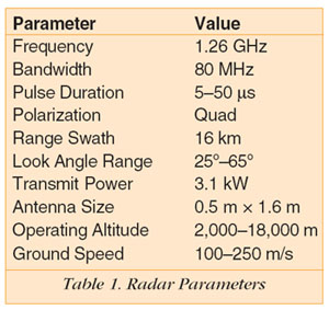
The UAVSAR radar is designed to be flown onboard a UAV (Unpiloted Aerial Vehicle) but it will be initially deployed on the NASA Gulfstream III aircraft. Figure 1 shows the UAVSAR instrument pod attached to the underside of the NASA aircraft during early flight testing. Key measurements the system is designed to make include:
- Precision crustal deformation for measuring earthquakes both during and after a seismic event, monitoring volcanic activity and surface changes induced by human activity
- Polarimetric interferometry that can provide measurements of forest structure and topography; polarimetric radars transmit pulses with both vertical and horizontal polarization
- Polarimetric interferometry to map the vertical structure of an area with vegetation
| |
|
To obtain valid data on successive passes over a specific area, the aircraft must fly in a trajectory that is within a cylindrical space of 10 meters in diameter. Furthermore, the radar antenna must be steered with 1 degree accuracy over a range of +20 degrees in azimuth. To meet these requirements, the Gulfstream was modified by NASA’s Dryden Flight Research Center (DFRC) to include a Precision Autopilot that controls the aircraft trajectory using the input from a precision real-time differential GPS (Ground Positioning System) designed and assembled by JPL with COTS components. The system also employs an electronically steered flush-mounted antenna that’s pointed in the desired direction based on real-time attitude angle measurements. The key parameters of the radar design are given in Table 1.
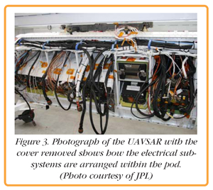
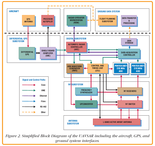 Figure 2 is a simplified block diagram of the UAVSAR radar. The radar has been designed to minimize the number of interfaces with the aircraft for improved portability. The aircraft supplies the pod with 28 V DC power and receives position information from the pod’s differential GPS unit.
|
The desired flight paths are generated by the Ground Data System and loaded into the Precision Autopilot and the Automatic Radar Controller (ARC). The ARC is the main control computer and is designed to operate in a fully autonomous mode or to accept commands from the Radar Operator Workstation (ROW).
The Control and Timing Unit (CTU) controls the timing of all the transmit and receive events and thus interacts with many radar digital and radiofrequency electronics. The active array antenna consists of 24 L-band transmit/receive modules that feed 48 radiating elements within the 0.5 m by 1.5 m array. The photograph of Figure 3 on the next page, shows how the various subsystems are arranged within the pod.
| |
|
Digital Electronics Subsystem
The Digital Electronics Subsystem (DES) provides the overall timing and control signals for the radar as well as the telemetry and data acquisition functions. All the digital units are housed in a custom VME card cage. Coordination and control is through the ARC, the master computer. The ARC flight software controls the system in both attended and unattended flight operations. The ARC software utilizes the Wind River VxWorks real-time operating system.
Precision timing of the radar pulse generation, ADC operation, and antenna commands are essential for proper radar operation. The CTU unit was designed by JPL using a Xilinx FPGA. It generates all the radar timing signals for the Arbitrary Waveform Generator (AWG), antenna, radar receivers and the data acquisition.
After each transmitted pulse, the radar opens a receive window and digitizes the return signal. The radar employs an offset sampling scheme whereby it records real rather than complex data. To meet the Nyquist sampling rate, it samples the return data at 180 MHz which is more than twice the radar bandwidth of 80 MHz. With pulse repetition rates up to 1 kHz per data channel and receive window durations of up to 150 msec, the radar generates a large amount of data. The ADC board is the Pentek Model 6821, 215 MHz, 12-bit VME board. JPL uses the conduction-cooled version of this board to handle the extreme environments encountered in the UAVSAR pod. Onboard data rate reduction uses an optional block-floating point quantization algorithm implemented in one of the Model 6821 FPGAs. The algorithm allows the user to select how many bits are retained from each data sample, anywhere from 12 to 2 bits. By supplying a user-defined exponent for each 128-sample block, the dynamic range is maintained.
Once the returned data is digitized, it’s buffered and written to disk along with an ancillary header and time tag. Data storage is provided by a COTS JBOD array with 1.8 TB capacity.
RF Subsystem
The RF subsystem consists of a frequency synthesizer that provides a 10 MHz reference signal for frequency generation, supplies a local oscillator for the upconverter and the receivers, and a timing signal for the AWG. Upconversion of the AWG center frequency of 137.5 MHz to the desired radar transmit center frequency of 1,257.5 MHz and routing of the signal to the antenna or receivers is done by the upconverter unit. Dual L-band receivers take the return signals from the transmit vertical and horizontal polarization signals, translate them down to center frequencies of 45 MHz and inject them into the two Model 6821 ADCs for digitizing.
Navigation Subsystem
While standard GPS position accuracy is 5–10 meters, the UAVSAR differential GPS uses correction information and real-time software to achieve accuracy better than one meter. This subsystem is a blend of COTS components coupled with the specialized software hosted on a single board computer.
Differential Interferometry
Repeat-pass airborne radar interferometry requires sophisticated signal processing algorithms to generate the desired deformation and associated scientific data. The UAVSAR Ground Data System consists of the hardware and software necessary to process and archive raw data and the derived scientific data.
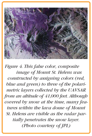
A detailed discussion of the processing methodology is beyond the scope of this article. Suffice it to say that the airborne flight tracks are not known sufficiently well in advance. It is thus necessary to use the collected data themselves to refine the time-varying baseline between flight tracks, reprocess the data with updated flight track information, then proceed with interferometric processing. Figure 4 shows a UAVSAR image of Mount St. Helens, perhaps most famous for its catastrophic volcanic eruption on May 18, 1980.
A Look into the Future
Ultimately, the goal of the UAVSAR system is not simply to make surface deformation measurements, but to use these measurements to achieve a better understanding of the underlying physics of solid earth processes.
| |
|
Geophysical algorithms that take the deformation maps and invert them for quantities of interest, e.g. fault depth and orientation of seismic sources are being developed by Stanford University as an integral component of the ground data system. Future application of UAVSAR might include support in response to natural hazards, such as an earthquake, as these algorithms and the system mature.
|